



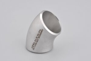
Steel Butt-Welding 45° Elbow
Steel Butt-Welding 45° Elbow Referenced Codes and Stand […]
Steel Butt-Welding 45° Elbow Referenced Codes and Standards.Manufacturing, inspection, and dimensional compliance for these assemblies are governed by a mandatory set of interlinked standards, each addressing a distinct aspect of the product:
ASME B16.9 – Factory-Made Wrought Steel Buttwelding Fittings: This is the governing document for the elbow portion, covering dimensional standards, pressure-temperature ratings, material requirements, tolerances, and marking for fittings in size range NPS ½ through NPS 48. It specifies that long-radius elbows shall have a center-to-end dimension (dimension A) derived from the relation A = 1.5 × NPS × tan(22.5°), and it imposes mandatory thickness minima after forming.
ASME B16.5 – Pipe Flanges and Flanged Fittings: This standard governs the flange end, prescribing pressure-temperature ratings for class designations 150# through 2500#, flange facing types (raised face, ring-type joint, flat face), bolting materials and torque guidelines, and dimensional tolerances for bore alignment and face perpendicularity. For sizes exceeding NPS 24, ASME B16.47 Series A or B applies as a supplementary reference.
ASME B16.25 – Buttwelding Ends: This document specifies the exact bevel geometry for welding-end preparation, including angle tolerance, root face (land) dimensions, and internal taper for heavy-wall components. It also addresses the preparation of internal ends to ensure smooth bore transition when wall thicknesses exceed standard schedules.
ASME Section IX – Welding and Brazing Qualifications: This code governs the qualification of welding procedures and welder performance used in joining the elbow to the flange, and it is invoked by all owner-engineering specifications for traceability purposes.
Material-Specific Standards: ASTM A234 (carbon and alloy steel wrought fittings), ASTM A403 (austenitic stainless steel fittings), ASTM A420 (low-temperature carbon steel), and for sour service, NACE MR0175/ISO 15156 imposes additional hardness and sulfide stress cracking resistance criteria that are not covered in the ASME fitting standards.
Type Designation and Coding System
A rationalized coding system is essential for procurement and quality documentation. The following alphanumeric designation structure is widely adopted in engineering procurement specifications:
ABBR – [Material Grade] – [NPS] – [Schedule] – [Flange Class] – [Facing Type]
Where:
· ABBR = Assembly, Butt-weld, Long-radius 45° (prefix)
· Material Grade = e.g., WP304L, WP316H, WPB, WP22 (Cl.1 or Cl.2)
· NPS = Nominal Pipe Size (e.g., 4, 8, 12, 20)
· Schedule = Wall thickness schedule (e.g., 10S, 40, 80, 120, XXS)
· Flange Class = 150, 300, 600, 900, 1500, 2500
· Facing Type = RF (raised face), RTJ (ring-type joint), FF (flat face)
Example: ABBR-WP316L-6-40S-300-RF denotes a butt-welding 45° long-radius elbow flange assembly, material 316L stainless steel, NPS 6, Schedule 40S wall thickness, Class 300 flange with raised face finish.
For assemblies fabricated from welded pipe (as opposed to seamless), additional suffix code “-W” is appended to distinguish weld-seam origin, which affects the radiographic examination frequency per ASME B16.9.
Data for 45° Elbows – Center-to-End and Outside Diameter
Per ASME B16.9, all 45° long-radius elbows are dimensioned from the intersection of the centerlines to the face of the fitting. The center-to-end dimension (A) is mathematically defined as:
A = 1.5 × NPS × tan 22.5°
For practical engineering use, the standard values as tabulated in the code are reproduced below for the most commonly specified sizes (inch units, nominal values):
NPS Outside Diameter (D) – mm Center-to-End (A) – mm
½ 21.3 16
¾ 26.7 16
1 33.4 22
1½ 48.3 32
2 60.3 38
3 88.9 51
4 114.3 67
6 168.3 95
8 219.1 121
10 273.0 146
12 323.8 171
14 355.6 194
16 406.4 219
18 457.2 244
20 508.0 269
24 609.6 318
These values are nominal for design purposes. The actual as-fabricated dimension is subject to the permitted tolerances specified in Section 6. For sizes above NPS 24, ASME B16.9 provides tabular values but with modified tolerance bands due to the increased scale of fabrication.
End Bevel Preparation per ASME B16.25
The butt-weld ends must be prepared with bevel geometry conforming strictly to ASME B16.25 to guarantee adequate weld penetration, minimize the risk of incomplete fusion, and allow for volumetric inspection after welding. The standard single-V bevel, designated as Type A in the code, is prescribed for wall thicknesses up to 22 mm (approximately 0.875 inch). Specific requirements are as follows:
· Bevel angle: 37.5° ± 2.5° from the axis perpendicular to the pipe surface, resulting in a 75° included angle (nominal).
· Root face (land width): 1.6 mm ± 0.8 mm. This land serves to prevent burn-through during the root pass and provides a consistent backing for the first weld layer.
· Root gap: Not specified by ASME B16.25 as a fixed value; it is instead defined by the qualified Welding Procedure Specification (WPS), typically ranging between 2 mm and 5 mm depending on the welding process and position.
· Internal taper: For wall thicknesses exceeding 22 mm, the bevel shall incorporate an internal taper or compound bevel (Type B or C) to facilitate access for the welding torch and to reduce the volume of deposited weld metal. The internal taper angle shall be 10° minimum, and the transition radius shall be smoothly contoured to avoid stress-raising notches.
The bevel preparation shall be free of laminations, burrs, and sharp edges. All beveled surfaces are required to be machined or ground; flame-cut bevels are only accepted if subsequent machining removes the heat-affected layer. For field welding, the bevel geometry must be verified using a bevel protractor or contour gauge prior to fit-up.
Dimensional Tolerances per ASME B16.9
ASME B16.9 prescribes distinct tolerance classes for different dimensions and size ranges. The following table extracts the critical tolerances that affect assembly fit-up and subsequent flange alignment:
Parameter Permitted Tolerance – NPS ≤ 10 Permitted Tolerance – NPS > 10
Center-to-end (A) – 45° elbow ± 1.6 mm ± 3.2 mm
Outside diameter at bevel ± 0.8 mm +1.6 mm / -0.8 mm
Inside diameter at bevel ± 0.8 mm +1.6 mm / -0.8 mm
End off-square (perpendicularity) ≤ 1.6 mm per 300 mm of fitting size ≤ 1.6 mm per 300 mm of fitting size
Alignment of ends (eccentricity) ≤ 0.8 mm per NPS, max 2.4 mm ≤ 0.8 mm per NPS, max 4.0 mm
Additionally, for the flange portion (ASME B16.5), the face-to-bore perpendicularity tolerance is 0.08 mm per 100 mm of flange diameter (approximately 1/64 inch per foot), and the bolt hole circle diameter tolerance is ±0.5 mm for standard classes. The cumulative stack-up between the elbow and flange tolerances, particularly in center-to-end and face perpendicularity, must be evaluated by the fabricator to ensure that the final assembly does not exceed the flange face angular misalignment allowed by the gasket manufacturer (typically 0.5° maximum).
ss Limits and Minimum Thickness Requirements
The wall thickness of the formed elbow is subject to the following mandatory minimum requirement: at no point on the finished fitting shall the wall thickness be less than 87.5% of the nominal wall thickness of the matching pipe. This is stated explicitly in ASME B16.9, Paragraph 7, and is enforced during final inspection by ultrasonic thickness gauging at a minimum of four circumferential locations per fitting. The 87.5% floor corresponds to a 12.5% under-tolerance, which is the standard manufacturing allowance for wrought steel fittings. For fittings manufactured from welded pipe or plate, the longitudinal seam region is subject to an additional wall thickness check; the minimum thickness in the weld-adjacent heat-affected zone shall not fall below the same 87.5% threshold, and the weld reinforcement is not credited toward wall thickness calculation.
For the flange hub at the butt-weld end, ASME B16.5 does not apply the 87.5% rule directly because flanges are dimensioned by pressure class rather than schedule. Instead, the hub outside diameter and the bore diameter are specified as absolute dimensions, and the resulting net section thickness at the hub-to-weld transition must be sufficient to sustain the design pressure as calculated per ASME B31.3. A reduction below nominal due to machining is permitted provided the minimum required hub thickness is maintained. This value varies by class and size and is tabulated in ASME B16.5.
Additional note: when the fitting is ordered with a wall thickness greater than standard schedule (e.g., extra-heavy or double-extra-heavy), the 87.5% minimum applies to the ordered nominal wall thickness, not to the standard schedule thickness. This distinction is a frequent source of procurement disputes and should be clearly stated in the purchase order.
No technical specifications available for this product.
Oil & Gas Industry
Offshore platforms, subsea pipelines, refining equipment, and processing facilities. Excellent resistance to sour gas and chloride stress corrosion cracking.
Chemical Processing
Chemical plants, pharmaceutical production, pulp and paper mills. Superior performance in acidic and chloride-containing environments.
Desalination Plants
Seawater reverse osmosis systems, brine handling, and thermal desalination units. Outstanding resistance to chloride-induced corrosion.
Power Generation
Thermal power plants, nuclear facilities, and renewable energy systems. High-temperature strength and corrosion resistance.
Marine Applications
Shipbuilding, port facilities, and coastal installations. Excellent seawater corrosion resistance and mechanical properties.
Mining & Metallurgy
Slurry pipelines, ore processing, and tailings handling. Resistance to abrasive and corrosive media.