



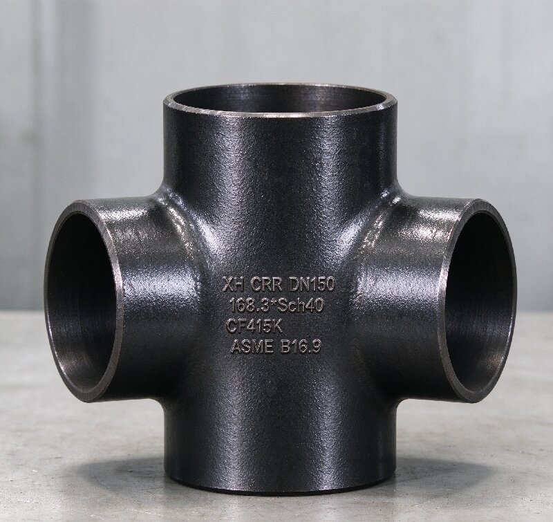
Reducing Welded Cross (Steel Butt-Welding Cross, Equal/Reducing Branch)
Product Overview A reducing cross is a four-way butt-we […]
Product Overview
A reducing cross is a four-way butt-welding fitting whose opposing outlet pairs differ in size — an NPS 12 run with NPS 8 branches, for example. It serves where two streams divide or combine in one plane and the line cannot take two separate tees without adding girth welds, radiography and pressure loss. Trade usage calls the product , where refers to the butt-welding end connection, not the method of manufacture.
Designation follows the same logic: run size first, branch size second, with the outlets on one axis normally equal. A cross with three outlet sizes, or with unequal outlets on one axis, is non-standard and must be drawn and agreed before quotation.
Seamless Forming versus Fabricated Construction
Seamless bodies come by two routes. In hydraulic bulging, a pipe of the same nominal size is filled with liquid and compressed axially while internal pressure rises, forming both branches in one stroke. In hot radial-compensation pressing, an oversize blank is flattened, heated, pierced and drawn outward by punches, the branch metal being supplied by radial flow. The routes leave different thickness distributions at the crotch, which governs the pressure rating. Bulging is limited by press tonnage and normally applied to DN400 and below in standard wall; radial-compensation pressing suits heavy wall.
Above NPS 24 the body is fabricated: run cut, branch openings set out and cut, stubs welded in as full-penetration joints. This allows sizes beyond any billet or press, independent wall thickness per outlet, and dissimilar grades — a WP11 run with WP22 branches. The cost is a pressure-containing weld whose root becomes inspection-critical.
Honest Boundaries: Where a Reducing Cross Is the Wrong Purchase
A reducing cross is not automatically the better purchase. On utility and low-pressure lines, two reducing tees in series cost less, are quicker to obtain in urgent sizes, and are easier to radiograph and repair in place. The single body earns its price where girth welds in a high-integrity line must be minimised, where radiography cannot reach the intersection, or where two tees would place a longitudinal seam and a branch weld in one high-stress region. A purchasing caution follows from the same physics: two tees welded together are often sold as a reducing cross, and once painted the two are hard to tell apart. The distinguishing feature is the seam — a circumferential weld encircling the run exactly at the intersection — and a price close to that of two tees should be read as a warning.
Where the service is cyclic, in sour duty, or precluded from single-wall radiographic access, and the size permits, a seamless body is the technically correct choice regardless of price; a fabricated body there requires a documented verification route.
If the cross is later split into two tees on the drawing — the usual value-engineering move on utility work — the branch spacing and the resulting bending moment at each branch must be rechecked, since two adjacent branches stiffen the run differently from one cross body.
Specification Range
| Item | Range |
| Size | NPS 1/2–24 seamless; NPS 26–60 fabricated |
| Run / branch | Reducing on either or both pairs; asymmetric layouts on request |
| Wall thickness | SCH 10 – SCH XXS; heavier on request |
| Materials | A234 WPB/WP11/WP22/WP91; A420 WPL6; A403 WP304L/WP316L; A860 WPHY 42–70 |
| Dimension standard | ASME B16.9; MSS SP-75 for high-yield line-pipe grades |
| End preparation | ASME B16.25 bevel, 37.5° ± 2.5° |
| Surface | Shot-blasted, shop primer, or pickled and passivated |
| Marking / certificate | MSS SP-25; EN 10204 3.1 |
Dimensions and Tolerances
For equal crosses to NPS 24, C and M are identical and one value applies to all four outlets under ASME B16.9. From NPS 42 they diverge — 762 mm against 711 mm at NPS 42 — so a cross in that range cannot be ordered from a single dimension. On reducing crosses, C applies to the run outlets and M to the branches, each to its own size. Above NPS 26, M is a recommended value only, which is why large fabricated crosses are ordered against a drawing. A cross with two different branch sizes is dimensioned separately for each branch, and the drawing should state which outlets share an axis.
Bevel outside diameter tolerance is +1.6/−0.8 mm at NPS 1/2–2-1/2, ±1.6 mm at NPS 3–4, +2.4/−1.6 mm at NPS 5–8, +4.0/−3.2 mm at NPS 10–18, +6.4/−4.8 mm at NPS 20–48; centre-to-end ±2 mm; bevel out-of-roundness within 1% of nominal outside diameter. No point of the wall may fall below 87.5% of nominal, judged at the thinnest point, which on a cross is the crotch. Inspection differs by construction: a seamless cross is gauged at each branch crotch rather than at mid-run, because a body that passes at mid-run can be thin at the port, and the port is where fit-up fails. A fabricated cross is checked for bevel profile after welding and stress relief.
Code Basis and Design Verification
Two clauses govern this product and both are commonly misapplied. The bevel is prepared to ASME B16.25 while B16.9 governs the dimensional envelope; citing B16.9 for bevel angle cites the wrong document. Fit-up misalignment is not a B16.9 tolerance at all but a welding requirement under ASME B31.3 Table 328.4.3, applied on site to the fitting and pipe actually being joined. The second point is the one that costs money in disputes, because the fabricator can meet every B16.9 dimension and still leave the joint outside the B31.3 limit once the pipe is offered up.
Where a B16.9 cross is later modified — opening enlarged, outlet re-sized, stub welded on — it becomes an unlisted component under B31.3 para 304.7.2. The original rating basis no longer applies: the weld introduces a heat-affected zone, the opening removes material and the local stress distribution changes. Verification must follow one of four routes — design by rules under Chapter IX, fracture mechanics, experimental stress analysis, or documented service experience. A purpose-built fabricated cross falls under this paragraph from the outset, and the route should be named in the enquiry.
High-yield grades for line pipe follow MSS SP-75 rather than A234: carbon equivalent ≤0.45% with the actual value marked above 0.42%, hardness ≤248 HV10 (22 HRC), mandatory impact testing, EN 10204 3.1 certificates and a 1.10/1.05/1.00 burst factor by number of test pieces. SP-75 covers seamless and welded manufacture alike and is not a welded fitting standard.
Manufacturing
1. Material verification — certificates checked; alloy and stainless heats 100% spectrometric tested.
2. Cutting — plasma or saw; thermally cut edges ground to sound metal before forming.
3. Forming — bulging or hot pressing; die temperature and ram synchronisation recorded per heat.
4. Fit-up — openings set out from a template; stub alignment checked on a mandrel before tacking.
5. Welding — full-penetration joints to a qualified WPS/PQR under ASME IX; preheat and interpass temperature by contact thermocouple.
6. Heat treatment — stress relief per B31.3 Table 331.1.1, chart recorded per piece.
7. Machining — bevels turned to B16.25 after heat treatment.
8. Examination — dimensional, thickness, hardness and NDE as ordered.
9. Marking and packing per MSS SP-25.
Welding, Heat Treatment and Examination
On fabricated crosses the governing failure mode is lack of root penetration or root concavity in the branch weld. Neither is visible externally nor found by dimensional inspection. Root condition is established by radiography covering the full circumference, or by phased array ultrasonic testing where radiography is impractical; dye-penetrant testing of the root pass is in-process control, not a substitute for final volumetric examination. Acceptance follows B31.3 Table 341.3.2 for the service category concerned. A hydrostatic test to 1.5 times the design pressure is offered on request, but it should not be read as evidence of root condition, since a cross with a partial-penetration root will usually hold that pressure without leaking.
Heat treatment is by grade. WPB is stress-relieved where thickness and Table 331.1.1 require; WP11 and WP22 after welding and after cold forming beyond the permitted limit; WPL6 is stress-relieved to protect notch toughness, with post-weld hardness checked because HAZ impact values fall as hardness rises. For sour service to NACE MR0175 / ISO 15156, hardness surveys cover weld, HAZ and base metal, with 22 HRC the ceiling for carbon steel.
Order Information Required
Run and branch sizes with outlet arrangement; required construction and permitted alternative; wall thickness per outlet; grade and impact test temperature; design code and service category, with the verification route if fabricated; NDE method and extent; heat treatment and hardness limit; bevel or plain end, coating and packing.
Coatings are applied only after NDE has been accepted, so that repaired areas are not painted over, and bevels are protected with a removable varnish, since a rusted bevel or one carrying overspray has to be re-machined on site.
No technical specifications available for this product.
Oil & Gas Industry
Offshore platforms, subsea pipelines, refining equipment, and processing facilities. Excellent resistance to sour gas and chloride stress corrosion cracking.
Chemical Processing
Chemical plants, pharmaceutical production, pulp and paper mills. Superior performance in acidic and chloride-containing environments.
Desalination Plants
Seawater reverse osmosis systems, brine handling, and thermal desalination units. Outstanding resistance to chloride-induced corrosion.
Power Generation
Thermal power plants, nuclear facilities, and renewable energy systems. High-temperature strength and corrosion resistance.
Marine Applications
Shipbuilding, port facilities, and coastal installations. Excellent seawater corrosion resistance and mechanical properties.
Mining & Metallurgy
Slurry pipelines, ore processing, and tailings handling. Resistance to abrasive and corrosive media.