



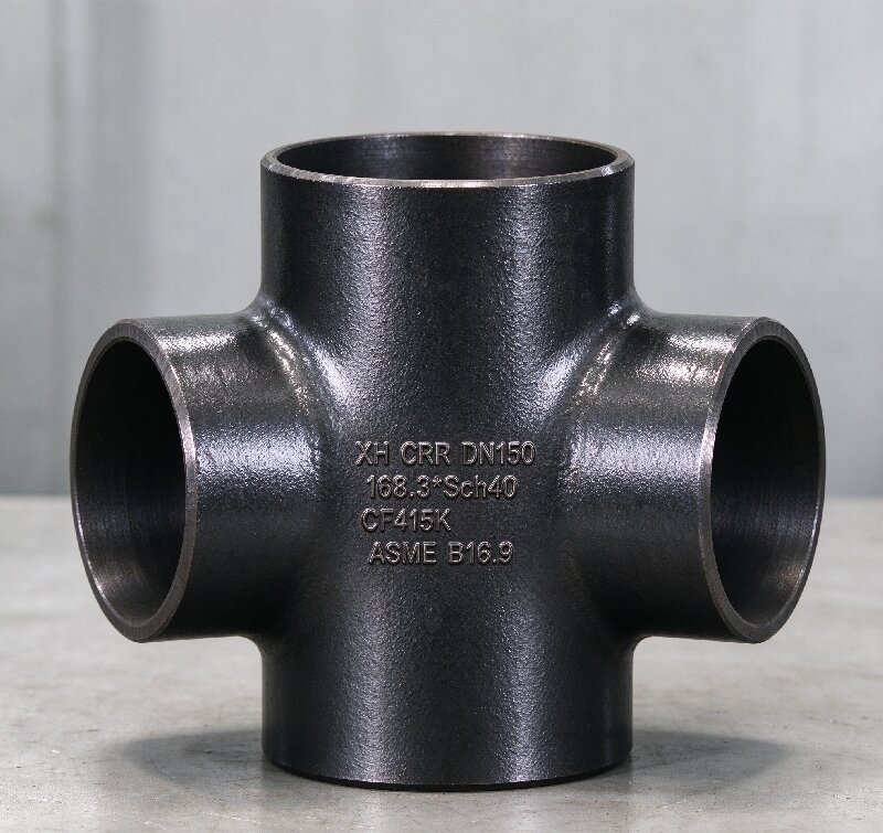
Steel Welded Equal Cross — Fabrication, Code Basis and Large-Diameter Dimensions
1.Product Overview A welded equal cross is a four-way f […]
1.Product Overview
A welded equal cross is a four-way fitting with four equal outlets at 90° intervals, produced by welding rather than by hot forming from a single billet. The pressure boundary is established by full-penetration butt joints at the run and at both branch connections; the ends are bevelled for butt welding into the line.
The Chinese designation is unambiguous here: the fitting is welded into the pipeline, and welded together in the first place.
2.Selection Basis
Seamless crosses depend on billet availability and on the forming press. Welded fabrication is the standard route where those limits are exceeded:
– Diameter. NPS 26 and above. Above approximately NPS 24 there is no seamless alternative.
– Wall. Non-standard and heavy wall without the requirement for a matching billet.
– Dissimilar grades. Carbon run with stainless branch, or low-alloy run with carbon branch, is a welding problem rather than a forming problem.
– Economics. Above the seamless ceiling, fabrication is generally lower cost and shorter lead time. Below it, the reverse holds.
Conversely, where the line sees cyclic loading, is in sour service, or has locations precluded from radiographic access — and the size permits — a seamless body is the technically correct selection.
3.Fabrication Routes
Two equal tees joined at a girth butt joint. The most economical route. The joint is a full-penetration single-V or double-V groove selected by wall thickness; cut lengths are pre-compensated for weld shrinkage so the C dimension is met after PWHT, not corrected afterwards by fit-up.
Run pipe with two set-in branch connections. Both branches welded through the run wall for a full-penetration crotch on both sides. Set-on branches are accepted only where the referencing code permits the detail; pressure-containing capability at the branch is reduced and the joint requires separate qualification.
Segmental or plate fabrication. For diameters or wall not obtainable in pipe; additional weld length and greater examination scope.
4.Code Basis and Design Verification
Weld end preparation follows ASME B16.25, not B16.9. For wall thickness above 3 mm to 22 mm, a single bevel at 37.5° ± 2.5° with a 1.6 ± 0.8 mm root face; above 22 mm, a compound bevel (37.5° / 10°) to control groove width and weld volume. Internal diameter at the weld end: +2 / −1 mm.
Component classification. A welded cross is an unlisted component under ASME B31.3 para 304.7.2. Welding and the removal of material for the branch openings invalidate the burst-test basis of the listed B16.9 geometry, so pressure design must be verified by one of: design by rules per Chapter IX, fracture mechanics, experimental stress analysis (FEA, strain gauging), or documented service experience. Where the configuration is B16.9-like, a proof test to the B16.9 procedure is an accepted route. We will state on the quotation which route the design takes.
Fit-up. Internal misalignment in accordance with ASME B31.3 Table 328.4.3. Unequal wall at a branch or at the ends is transitioned by taper: 1:4 minimum on the bore, 1:3 maximum on the outside diameter.
High-yield pipeline service. Where the specification calls for MSS SP-75, carbon equivalent is limited to 0.45% and hardness to 248 HV10 (22 HRC); impact testing is mandatory; girth welds in the fitting are examined per ASME BPVC Section V; burst testing uses a factor f = 1.10 for one test, 1.05 for two, 1.00 for three or more. For NPS 14 and below, MSS SP-75 references ASME B16.9 for dimensions.
5.Specification Range.Dimensions, NPS 26–48
This is the range in which welded construction has no seamless equivalent. Dimensions in mm.
Two provisions of the standard bear directly on the purchase order. For NPS 26 and above, the outlet dimension M is recommended but not mandatory. From NPS 42 to 48, C and M diverge and must be specified separately. Do not order above NPS 24 as “equal cross, standard” — state the dimensions.
6.Welding, Heat Treatment and Examination
– Root pass by GTAW on all joints; fill and cap per the qualified WPS. Preheat and interpass temperature controlled by material P-number, recorded for alloy grades.
– Full penetration at both crotches is a design requirement. A partially penetrated crotch weld is the characteristic failure mode of a fabricated cross and is not detectable by external visual inspection; the joint detail is specified to make it achievable, and the crotch is examined specifically for penetration.
– 100% radiographic examination of the junction, source selected by wall thickness (Ir-192 heavy wall, Se-75 thin). Where crotch geometry precludes meaningful radiography, phased array ultrasonic testing is applied instead.
– PWHT per ASME B31.3 Table 331.1.1 for carbon and low-alloy wall above the specified threshold, with thermocouple placement recorded and the chart supplied with the documentation package.
– Hardness survey to NACE MR0175 / ISO 15156 where the service is sour.
– Weld caps dressed and toes blended where the drawing calls for a smooth bore or where fatigue is a design consideration.
– Hydrostatic test at 1.5 × design pressure when specified; substitution by examination only where the referencing code permits it.
7.Order Information Required
Size, wall thickness or schedule, material grade, quantity, applicable design code, C and M dimensions where above NPS 24, branch detail (set-in or set-on), examination coverage, PWHT requirement, sour service classification, and any third-party witness point. Where the assembly is to be treated as an unlisted component, state the required verification route at the enquiry stage — it governs both the design work and the delivery schedule.
No technical specifications available for this product.
Oil & Gas Industry
Offshore platforms, subsea pipelines, refining equipment, and processing facilities. Excellent resistance to sour gas and chloride stress corrosion cracking.
Chemical Processing
Chemical plants, pharmaceutical production, pulp and paper mills. Superior performance in acidic and chloride-containing environments.
Desalination Plants
Seawater reverse osmosis systems, brine handling, and thermal desalination units. Outstanding resistance to chloride-induced corrosion.
Power Generation
Thermal power plants, nuclear facilities, and renewable energy systems. High-temperature strength and corrosion resistance.
Marine Applications
Shipbuilding, port facilities, and coastal installations. Excellent seawater corrosion resistance and mechanical properties.
Mining & Metallurgy
Slurry pipelines, ore processing, and tailings handling. Resistance to abrasive and corrosive media.