



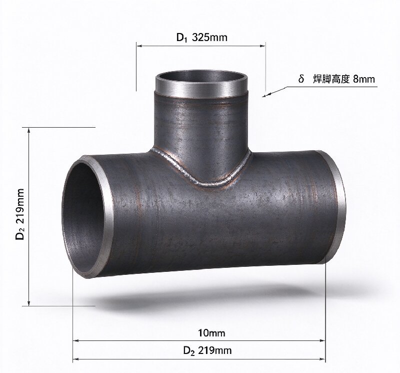
Steel Welded Reducing Tee — Welded Construction, Dimensions and Supply Notes
1.Product Overview A welded reducing tee is a branch fi […]
1.Product Overview
A welded reducing tee is a branch fitting whose run and branch outlets carry different diameters, made by welding rather than by extruding from a single pipe billet. In our shop the run is cut from pipe, the branch stub is set into a prepared opening, and both sides of the joint are welded through. The finished fitting is then stress-relieved and the weld caps dressed back flush with the body.
wo things are worth stating plainly, because they get confused constantly in this trade. First, a welded tee and a seamless tee are not interchangeable on a specification sheet — a welded tee carries a weld at the branch junction, and that is a code-recognised issue that the buyer must accept and inspect. Second, welded construction is not the “cheaper option.” It is the only practical route above roughly NPS 24, and for heavy-wall or large-diameter work it is what the line actually needs.
2.Why Welded Construction
Seamless tees are extruded from pipe billet, so the maximum size is bounded by what the mill can produce and by how much wall thickness the extrusion can carry without laps or thinning at the crotch. Past that limit, welded fabrication is the answer.
Welded construction gives us three advantages that matter to the customer:
- Large sizes. We routinely weld up to NPS 48 and, on inquiry, beyond. There is no billet ceiling.
- Wall thickness freedom. A welded tee can pair a heavy-run with a lighter branch, or match the exact wall of both headers without the wall-thinning that extrusion sometimes leaves at the crotch.
- Material pairing. When the run and branch are different grades — carbon into stainless, for example — welding is the only way to get there.
3.Typical Specification
| Item | Range |
| Size range | NPS 2 – NPS 48 (DN50 – DN1200); larger on inquiry |
| Branch to run ratio | Typically 0.3 – 0.8 of run nominal size |
| Wall thickness | Sch 10 – Sch 160, or as specified |
| Materials | ASTM A234 WPB / WP11 / WP22 / WP91, A420 WPL6, A403 WP304L / WP316L, A860 WPHY 42–70 |
| Design standard | ASME B16.9; MSS SP-43 for light-wall stainless |
| Weld standard | ASME B31.3 / B31.1 as applicable; ASME IX qualified WPS and PQR |
| Radiography | 100% RT on branch junction as standard, film or digital |
| Surface | Shot blasted, or pickled and passivated for stainless |
4.Fabrication and Welding
- Run preparation. Pipe cut square to length, the branch opening flame-cut or machined and the cut edge ground back to clean metal.
- Branch fit-up. The branch stub is set to the drawing’s M dimension within ±1.5 mm, root gap checked at four quadrants.
- Welding. Root pass TIG, fill and cap by SMAW or GTAW depending on material. For austenitic and duplex grades the root is purged; for P91 the interpass temperature is logged pass by pass.
- Stress relief. PWHT per ASME B31.3 Table 331.1.1 for carbon and low-alloy wall thicknesses above the threshold.
- Weld dressing. Caps ground flush where the drawing calls for a smooth bore, and the toes blended to remove sharp transitions.
- NDT and dimensional. RT on the junction, PT or MT at the toes after dressing, then full dimensional check at the bevels.
5.nspection and Documentation
Every welded tee ships with a documentation package: material certificates to EN 10204 3.1, the WPS and PQR used, welder qualification records, RT films or digital files, PWHT chart where applicable, and a dimensional report. Radiographs are stored against the heat number so a specific fitting can be traced back years later.
6.Order Information Required
To quote a welded reducing tee we need: run size × branch size, wall thickness or schedule for each, material grade for run and branch separately, quantity, whether RT is required at 100% or by sampling, any PWHT requirement, and the applicable design code. If your project requires a specific weld procedure or a third-party witness point, tell us at the enquiry stage — it changes both the process route and the delivery date.
No technical specifications available for this product.
Oil & Gas Industry
Offshore platforms, subsea pipelines, refining equipment, and processing facilities. Excellent resistance to sour gas and chloride stress corrosion cracking.
Chemical Processing
Chemical plants, pharmaceutical production, pulp and paper mills. Superior performance in acidic and chloride-containing environments.
Desalination Plants
Seawater reverse osmosis systems, brine handling, and thermal desalination units. Outstanding resistance to chloride-induced corrosion.
Power Generation
Thermal power plants, nuclear facilities, and renewable energy systems. High-temperature strength and corrosion resistance.
Marine Applications
Shipbuilding, port facilities, and coastal installations. Excellent seawater corrosion resistance and mechanical properties.
Mining & Metallurgy
Slurry pipelines, ore processing, and tailings handling. Resistance to abrasive and corrosive media.